
Produced by


Published June 5, 2026
Using the control valve sizing parameter CV alone to compare different valve style options can result in very painful surprises during commissioning.
BY: Mark Nord, Emerson
When sizing control valves, it is important to understand their flow capacities so one can choose the correct valve for a particular application. To aid in this endeavor, the industry has settled on the control valve sizing flow coefficient (CV) to determine the flow of a fluid through a control valve at a specific pressure drop. When sizing a valve, the user enters fluid data, the required flow, fluid temperature and available pressure drop (inlet pressure minus outlet pressure) into the calculations to determine the required CV. The user then selects a valve which has a CV at least as large, ideally slightly larger, to make sure the valve is sized correctly.
Sounds simple? Normally CV calculations are reasonably straightforward. However, there are many cases where the CV calculations are not so easy, and the expected result is anything but intuitive. Consider these statements:
How can this be? Next is a look at the unexpected results that control valve sizing and selection applications can create.
Simple CV equation
The basic liquid flow equation for control valves is as follows:
FLOW = CV
In this equation, DP = differential pressure and SG = specific gravity. Assuming the equation is solved for water (SG=1), then control valve sizing is quite easy. If a valve has a CV = 10 and there is 25 PSI drop across the valve, the control valve will pass:
FLOW = CV = 10
= 50 GPM
This is when it is fully open. If the valve CV = 20, it will pass 100 GPM with a 25 PSI pressure drop. Easy, right?
Well, the problem is that a valve’s published CV may not represent the actual flow capacity of the valve under certain conditions, and the actual installed flow capacity might effectively be much less than the published CV suggests. Let’s investigate that further.
Challenges with control valve sizing for liquids
Two of the most common challenges with control valve sizing with liquids are cavitation and flashing. When a liquid moves through the restricted throat of the valve, it must increase velocity to maintain the mass flow rate. This increased velocity creates a pressure drop that occurs in the restricted zone. Once the liquid passes through the valve, the flow area increases, the velocity decreases and some of the pressure is recovered.
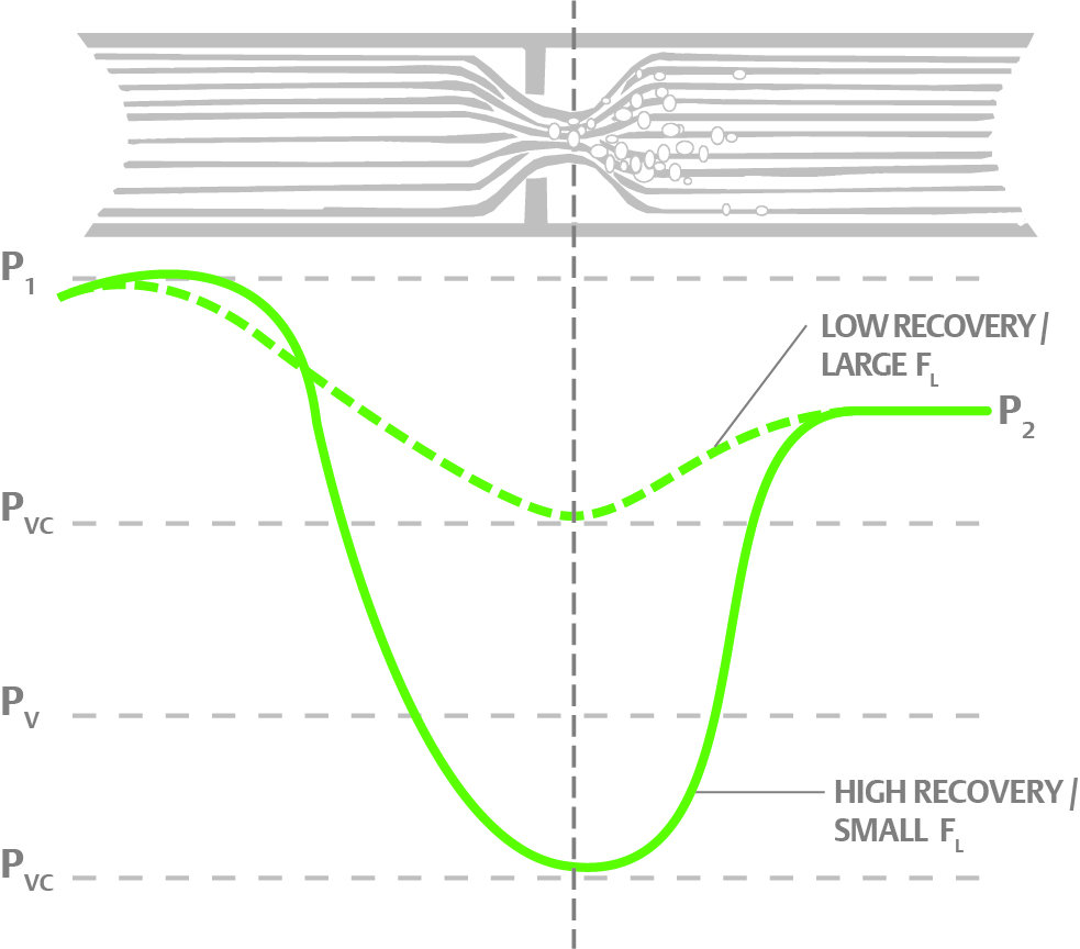
Figure 1: When liquid flows through a valve, it increases velocity to pass through the reduced area, creating a pressure dip. The relatively consistent geometry of a globe valve creates a small dip, while the changing geometry of a rotary valve such as butterfly or ball valves create a much more pronounced dip.
However, not all valves behave the same. Sliding-stem globe valves generally have smooth flow paths, so the pressure dip is comparatively mild. Ball and butterfly type valves do not have a smooth path, so the resulting turbulence creates a much more pronounced dip.
If the pressure dip does not drop below the vapor pressure of the liquid, there are no issues. Two valves with the same CV will largely behave the same when installed in similar conditions. However, if the pressure dip goes below the vapor pressure of the liquid, things change.
When the pressure dips below the vapor pressure, bubbles are created as the liquid begins to boil into a vapor in the throat of the valve, which restricts or chokes valve flow. If the pressure rises back above the vapor pressure, the bubbles collapse, creating a damaging situation called cavitation. If the pressure stays below the vapor pressure, the liquid essentially flashes across the valve, and two-phase flow then exits the outlet of the valve. Once a valve begins to choke, reducing the pressure downstream will not increase flow through the valve.
Either cavitation or flashing can greatly limit the flow through the valve, but as the graph shows, some valves will cavitate while others may not. This is a case where two valves with the same CV will not behave the same, because a valve experiencing cavitation will require a much larger CV to pass the same amount of flow.
The published control valve liquid recovery factor (FL) is an indication of how the valve behaves in a specific application. Valves with high FL (approaching 1) will tend to cavitate much less than valves with low FL. That is why it is important to run a liquid valve sizing calculation with the published CV and the FL for the particular valve of interest. Those two parameters should always be used together to get an accurate understanding of the flow capacity in a particular service. Figure 2 shows a flow calculation for four valves of the same size and CV and operating under the same process conditions, but each with a different FL value. The difference in valve capacity is significant if choking is present.
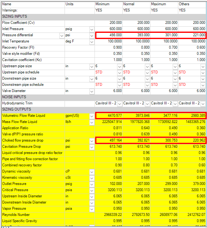
Figure 2: Four valves with the same body size and CV are subjected to the same process conditions yet flow very different quantities. The first valve is only just starting to choke/cavitate, while the other valves have reached choked flow at lower pressure drops and thus pass far less flow.
The key takeaway from this discussion is that two valves with the same CV will flow the same quantity of liquid only if no cavitation or flashing is present. However, different body styles will cavitate under different conditions, so it is possible that one valve will cavitate and flow much less when compared to a low recovery globe valve, which may not cavitate at all. As the valve pressure drop approaches the choked flow pressure drop, cavitation will start to occur and limit valve flow, and the choked flow pressure drop varies with different valve styles and FL values.
Challenges with control valve gas/vapor sizing
Choked flow can occur in gas/vapor applications as well. In this case, the choked flow occurs when the vapor approaches sonic velocity in the throat of the valve. Once sonic velocity is reached, the flow becomes fully choked, and like the liquid application, further reduction of downstream pressure will not change the flow through the valve.
Sonic velocity varies with process conditions and vapor types, so accurate information of the vapor content, pressures and temperatures must be entered to determine when choked flow will occur. Similar to the liquid flow recovery factor FL, each valve has a published rated pressure drop ratio factor called xT, which indicates how smoothly vapors pass through a valve.
Valves with higher xT (like globe valves) have smoother flow paths. This creates lower velocities when compared with ball or butterfly valves, each of which tends to have low xT values. As a result, a valve with a high xT value will flow more than the same size and CV valve with a lower xT (Figure 3). Unlike liquid applications, this is true for both choked and unchoked conditions. In vapor applications, both CV value and xT must be taken into account to determine a valve’s flow capacity. Also note that xT varies with flow opening, so the correct value for the calculation depends on the valve’s position.
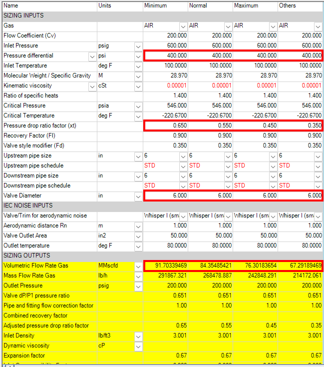
Figure 3: In this vapor application, four valves with the same body size and CV are subjected to the same process conditions yet exhibit very different flow quantities. The difference is XT, which varies with valve body style, internal construction, and valve position.
One major result of high pressure drops in gas/vapor applications is noise. As flow through the valve becomes choked, the energy of the pressure drop must be dissipated, and much of that energy results in noise that can quickly reach dangerous conditions. High noise levels can obviously damage hearing, but they can also create very high vibrations, which can shorten service life and even damage downstream piping.
A solution for these applications is low noise trim, which spreads the flow across a wider area, reducing velocity and dissipating the energy through smaller pressure drops and frequency shifting. While this can reduce the level of noise considerably, it does tend to further restrict flow and reduce valve flow capacity.
Valve installation effects on valve flow
Another unexpected impact on valve flow capacity in both liquid and vapor applications can occur when a smaller valve is installed in a larger line. In this case, the pipe reduction/expansion around the valve creates turbulence, which can restrict valve flow and limit capacity. For this reason, it is important to enter the actual inlet and outlet pipe sizes into the sizing calculation for every application so the effects can be determined.
Conclusion
Often a user is faced with a decision to choose between two valves that have the same body size and CV, but at significantly different price points. While a valve’s CV provides some idea of the capacity of a valve, other factors like the valve’s liquid recovery factor FL and the rated pressure drop ratio factor xT, will predict potential cavitation and/or high noise conditions. In addition, the details of the valve’s installation can also impact the amount of flow a valve can pass. Using CV alone to compare valve capacity can result in very inaccurate information. This often leads to erroneous decisions during valve selection and ultimately creates issues when the valve is placed in service.
To avoid these problems, the user is strongly encouraged to run the full sizing calculation, including not only the process data, but the information for the chosen control valve and the installation details. This will show the true differences among different valve body types, allowing the user to make the right decision for their particular application. Valve sizing calculations can seem daunting, but the effort is time well spent when compared to the cost of getting it wrong.

ABOUT THE AUTHOR: Mark Nord is the control valve solution architect for Emerson’s flow controls products. He is responsible for solving the most challenging control valve applications using his 35 years of experience in plant operation, control valve and steam conditioning applications. Nord holds a BSME degree from the University of North Dakota.
All images are copyright of Emerson.


Designed for high performance in industrial environments the metal-seated process valves work just as well at high temperatures and during rapid thermal cycling.
December 19, 2025
Discover how single-piston effect (SPE) and dual-piston effect (DPE) seat designs are engineered to meet the demanding pressures and temperatures of subsea applications.
December 15, 2025
Valves, actuators, controls and pumps are the unsung heroes of managing the function of data centers, specifically when it comes to all the types of cooling systems.
July 29, 2025
