
Produced by


Produced by
Published July 6, 2022
Electric valve actuators control the opening and closing of valves. With a motor drive that provides torque to operate the valve, these actuators are frequently used on multi-turn valves such as gate or globe and also on ball, plug and other quarter-turn valves.
By Jeremy Payne, Engineering Team Leader, AUMA Actuators; Updated by Maria Aguirre, Cowan Dynamics

Electric valve actuators are ubiquitous in today’s industrial space. They can be found in various industries and applications, including water treatment and wastewater plants, hydroelectric power generation, oil refineries, shipbuilding and numerous processing industries such as chemicals, food and beverage, pulp and paper, and pharmaceuticals. For anyone charged with the selection and operation of these products, it is important to understand the power source, controls, feedback, commissioning, security, backup power and failsafe required for the application.
This article will review different types of control systems and configurations available to electrically operate valves, which some in the industry refer to as motor-operated valves (MOVs), and how to make an informed decision on which type of actuator to use.
An electric actuator must have a power source available. Prior to selecting an actuator, it is important to determine the type of electricity that is available on site.
This will decide the type of electric actuator supplied for the application. The power source will be used to operate the motor through a set of reversing contactors, either located within the actuator, or in some cases located in a remote cabinet.
The power source must be capable of supplying the proper voltage and current required by the electric actuator to operate the valve. An electric actuator may be required to operate the valve as an open/close or modulating actuator; make sure the actuator is manufactured and supplied according to the required specifications.
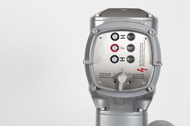
Controls are what operate the electric actuator so the next step is to determine how the actuator will be controlled.
There are two main types of controls:
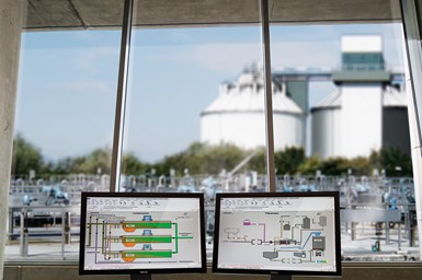
Remote control system.
Discreet open and close signals from a PLC or other system are most commonly used with open/close valves and can be used for modulating service as well. This is done with open/stop/close signals sent from pushbuttons or switches (pilot devices) from the PLC or remote-control station to the actuator. Control power is typically a 24VDC or 110VAC signal. Remote-control power can be provided on-site, or in some cases, actuators come equipped with a control power transformer (CPT) that provides this voltage for the customer’s control system to use.
Analog control signals are common with modulating valves. The analog control signal can also be referred to as a positioning signal or set point. Most analog controls utilize a 4-20mA signal, with 4mA being fully closed and 20mA being fully open. A 0-20mA is typically not used because 0mA could be misinterpreted as a loss of signal. The valve’s position in between close and open can be reached by setting the mA control signal to a signal position in between 4mA and 20mA, respectively. This signal could be sent from the control room, or in some cases, it could be the output of a flowmeter upstream of the valve used to regulate flow.
Digital bus communication can be used on open/close valves or modulating valves. Digital bus communication is also referred to as fieldbus or two-wire control, as the control signal communicates along wires connected in between a group of actuators and a digital bus controller.
To use a fieldbus communication, first determine which protocol will be used. Some of the available protocols are:
If the site is communicating via fieldbus, make sure the actuator can use the same protocol.
Some actuators can provide the option to operate with discreet inputs and fieldbus communication.
Feedback are the signals coming from the actuator to the control system, also referred to as output signals.
Analog feedback. Actuators can supply a 4-20mA signal to give the control system the existing valve position, like the setpoint analog control signal. 4mA or 20mA may be set to indicate the open or close position based on the application. Some actuators can also offer torque feedback in the form of a 4-20mA signal indicating actuator output torque, if the application requires.
Discreet feedback signals. Many actuators have status relays available to the customer signaling actuator position, torque-fault, general fault, run indication or intermediate position. In the case of non-intrusive (defined below in Commissioning) actuators, they will have relays that can be programmed to the customer’s desired feedback signal requirements.
Bus communication feedback. Fieldbus monitoring can be done across the fieldbus signal to include many more signals than are capable using the discreet feedback. For example, this can be the actuator’s position or status, and fieldbus system status, in addition to many others depending on the fieldbus protocol.
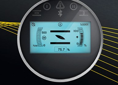
Visual position feedback screen.
Limit/torque switches. These are available as voltage-free dry contacts to give position/torque feedback status.
Visual position feedback. Most actuators come with a physical position indicator that shows the position of the valve and actuator; this may be in the form of a mechanical dial or on-screen indication. If the valve actuator is mounted to an additional gearbox, it often is supplied with a pointer cover to offer visual position indication.
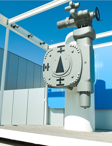
Visual mechanical position feedback indicator.
Commissioning of an actuator is required to ensure proper operation of the valve and integration to the control system. Commissioning requirements may include verification or setting of end positions, setting of torque and the feedback signals. Commissioning is performed based on the type of actuator provided.
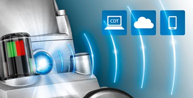
Hands-on and/or wireless commissioning.
There are different levels of security available for the customer when it comes to an electric actuator.
Physical security: Actuators can be supplied with lockable pilot devices, such as selector switches. Additionally, lockable covers may be supplied to cover the local controls. There is also the option to have padlocks on the handwheel/declutch devices, which are used to operate the valve manually.
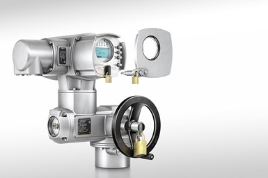
Actuator and hand wheel with locks and an alternative option for a faceplate cover. Photo credit: courtesy of AUMA
Backup or emergency power may be important in an instance where the main power on-site is interrupted. A decision must be made as to the type of actuator operation required upon the loss of main power. Does the actuator still need to operate the valve normally or just place the valve in a safe position?
These options can operate the actuator and/or place the actuator in a safe position in a loss of main power:
UPS (Uninterrupted Power Supply): If a solution for actuator normal operation during a power outage is needed, a UPS backup power system could be a good option for the actuator. This will allow a customer to open or close the valve in the event of an emergency power outage.
DC (Direct Current Power): Actuators are also available in a DC voltage version. These can be used if a site has backup DC voltage available to operate an actuator during an emergency power outage.
An actuator may be supplied with a device to place it in a safe position. This device often uses a spring or other technology to place the actuator in the defined safe position.
Power Source
Type of Controls
Feedback
Commissioning
Security
Backup Power
Make sure the actuator and backup power sources are compatible (voltage, current, etc.)
Failsafe
Electric actuators have an important role in safe and efficient operation valve operation. Understanding the various elements, such as those discussed here, allow the user to successfully define, set up and operate a basic control system.
In the realm of industrial automation, electric actuators are a standout solution renowned for their superior precision, adaptability, and energy efficiency. Offering precise control over speed, position, and force, they excel in dynamic operating conditions, making them ideal for applications that demand fine control. The surge in their popularity is attributed to their on-demand energy consumption and eco-friendly design, aligning with new global regulations seeking sustainable solutions across industries, especially in the industrial sector. The use of electricity opens doors to leveraging renewable energy sources like solar and wind. Their streamlined design and reduced maintenance requirements further increase their appeal, positioning electric actuators as one of the main choices when seeking efficient, environmentally friendly, and low-maintenance automation solutions.